
-
Maple was the first commercial product from LeafLabs
-
Bring the speed of 32-bit single-board computing to hobbyists and engineers outside of the embedded industry
-
Board Design, Firmware, Commercial Production, Documentation
Maple was one of the first ARM Cortex-M3 microcontroller boards, all designed and built by LeafLabs.
Much loved by users around the world, the STM32-based single board computer surpassed the capabilities of similar products when it was first released in 2009. Maple was followed by the Maple Mini in 2011, a "breadboard-able" PCB for applications where space was limited. The free software toolchain and open source library of the Maple series reflected the open source roots of LeafLabs.

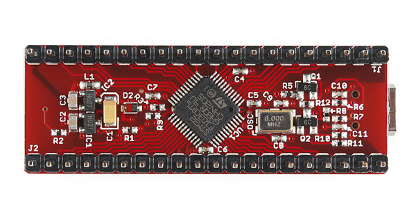
Maple was one of the first ARM Cortex-M3 microcontroller boards that was accessible to hobbyists and engineers outside of the embedded industry, and the Maple series helped with the transition from 8-bit to 32-bit processing. The Maple series was used in everything from personal projects, to academic research and numerous commercial products. Some of our current projects began with the libmaple.
Services
Although the Maple line is end-of-life, LeafLabs offers a number of engineering services including embedded engineering, FPGA development, and PCB design. We'd love to hear about your project and how we might help.
Resources
As of March 2015, the LeafLabs Maple line and the libmaple library are end-of-life and no longer supported by LeafLabs. The design files for Maple and Maple Mini will remain available on GitHub, under a CC-BY-SA 2.0 license, for anyone who wants to recreate or reimagine these boards. libmaple will also stay on GitHub, and we will continue to take community patches.
You can still read the docs. As of August 2016 the forums have been converted to a static archive. We recommend checking out the resources and community at www.stm32duino.com.